Book Name: Sheetmetal User's Guide - Note this is taken off the web from Pro/Engineer


Topic

Bend Allowance
Bend Order Tables
Fixed Geometry
Default Radius

Bend Allowance

Bend allowance is a method to calculate the length of flat sheet metal required to make a bend of a specific radius and angle. Bend tables are used for the accurate calculation of this length.

Use one of the following three methods to calculate the bend allowance:

Bend tables are used to calculate the bend allowance. When Pro/ENGINEER looks for a value and does not find it in the bend table data, it uses the formula equation.

If you want to use the formula equation only to calculate developed length, but you do not like the formula which is used by Pro/ENGINEER (see Y-factor) then you must create a bend table. The data in the table will be:

Y-factor

If you do not assign a bend table to the part, Pro/ENGINEER uses the following equation to determine developed length:

where:

L-Developed length.

R-Inside bend radius.

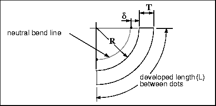
Y-factor-A part constant defined by the location of the neutral bend line (see the following illustration). The default Y-factor is 0.5.

T-Material thickness.

-Bend angle (in degrees).
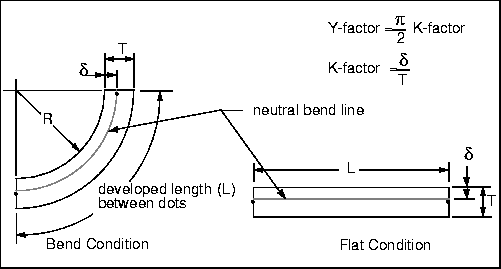
Developed Length of Material and Y-factor

The default Y-factor value is 0.5. Use the following configuration file option to modify the default system value:

initial_bend_y_factor <value>

If you specify a value other than 0.5 and re-load the configuration file, all new sheet metal parts created in the current session use the new value.

When you save a sheet metal part, the Y-factor value is stored with it. Use the Y-factor option in the Bend Allow menu to modify the Y-factor.

Enter Val Menu

Use the Enter Val menu found under the Bend Allow menu to do the following:

How To Modify the Y-factor

  1. Choose Set Up from the PART menu.

  2. Choose Sheet Metal from the PART SETUP menu.

  3. Choose Bend Allow from the SMT SETUP menu.

  4. Choose Y-factor from the BEND ALLOW menu.

    If a bend table is currently assigned to the part, the system prompts you to confirm that you wish to discard it. Choose Confirm from the CONFIRMATION menu.

    The ENTER VAL menu appears.
  5. Choose one of the options. The system completely regenerates the part, using the new value.

Note:

For stretched bends (see the following illustration) is negative, which makes the Y-factor negative too.

Negative Y-factor

Pro/SHEETMETAL Bend Tables

Bend tables are used to accurately calculate the length of flat material (developed length) required to make a bend of a specific radius and angle.

For the same bend, the developed length is different for different materials and material thicknesses.

Bend tables can be read in at any time. Note, however, that once a part is associated with a bend table, its geometry depends on the table data. The bend table information is not stored with the part.

Every time the part is regenerated, it looks up the associated table for appropriate length values. If you modify a bend table, all parts associated with it are updated upon regeneration.

Pro/SHEETMETAL provides the following three bend tables for your use:


Table Name

Material

Y-Factor

K-Factor
TABLE1
Soft Brass and Copper
0.55

0.35

TABLE2
  • Hard Brass and Copper
  • Soft Steel
  • Aluminum

  • 0.64


    0.41

    TABLE3
  • Hard Copper
  • Bronze
  • Cold Rolled Steel
  • Spring Steel

  • 0.71


    0.45

    The bend tables provided with Pro/SHEETMETAL are used with permission from Machinery's Handbook, 23rd Edition.

    Note:

    Bend Tables are applicable only for constant-radius bends. Bends with a varying radius (such as a cone have their developed length calculated using the Y-factor.

    Bend tables are normalized for 90° bends. For other than 90° bends, Pro/ENGINEER takes those values and multiplies them by /90, where is the specific bend angle, in degrees.

    The three Pro/SHEETMETAL bend tables use the following formula equation:

    (The Y-factor value for each table is shown above).

    Note:

    Since Pro/SHEETMETAL table data in the provided tables is the developed length, no CONVERSION statement is used.

    Types of Bend Tables

    You can make a particular Wall or Bend feature reference a different bend table from the bend table or Y-factor associated with the overall part. At the time of creating a Wall or Bend feature, you have two options:

    After feature creation, use Redefine Attributes to change its bend table from the Part Table to a Feature Table or vice versa. Note that you cannot change directly from one feature table to another-you have to change to the part table as an intermediate step.

    Creating Bend Tables with Pro/TABLE

    You can create your own bend tables to support additional material types or if you have an established bend table standard that uses a different method for calculating the developed length.

    If you create your own library of bend tables, tell Pro/ENGINEER where to find them by using the configuration file option

    pro_sheet_met_dir directory_<pathname>

    and give the path to the directory in which they are stored. When you specify a bend table by name, the system looks for it in the current directory and the above directory.

    Create your bend tables for 90° bends. For other than 90° bends, Pro/ENGINEER takes those values and multiplies them by /90, where is the specific bend angle, in degrees.

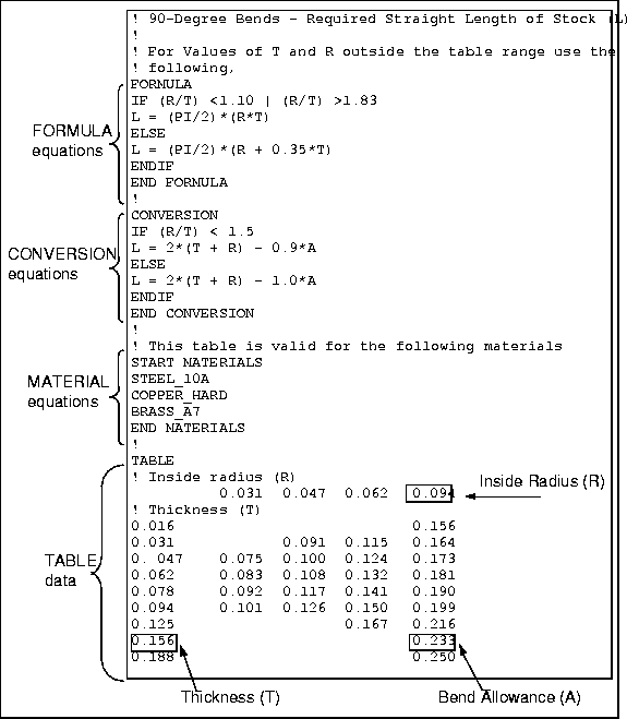
    You do not have to insert a bend allowance value (A) in every cell in a bend allowance table. If you leave a particular cell blank, the system calculates a value for the exact combination of R (inside bend radius) and T (material thickness) that it represents by using the formula.

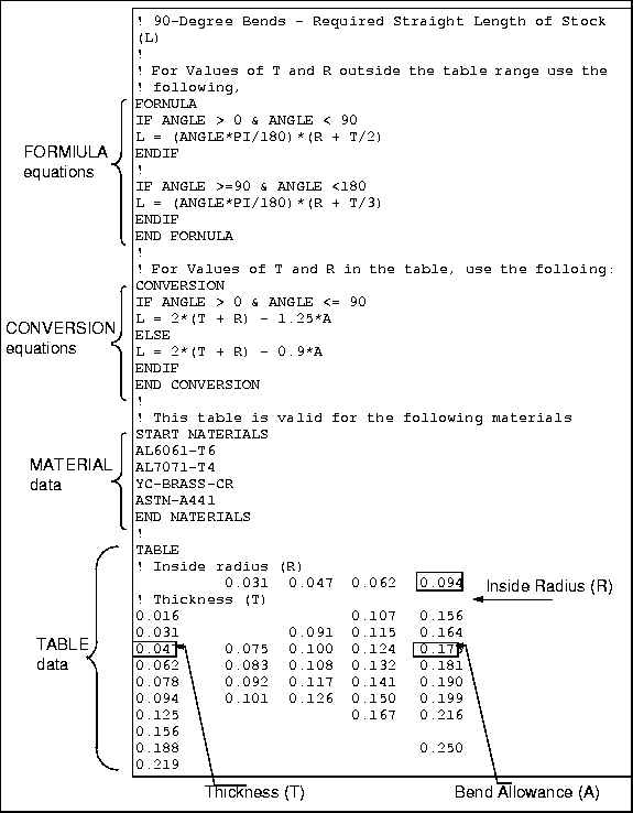
    The illustration Developed Length of Material and Y-factorshows variables associated with a bend. The illustration Pro/TABLE Bend Table is an example of a bend table. It shows the layout and data that needs to be provided to Pro/ENGINEER for it to correctly unbend a sheet metal part.

    The following table, Bend Table Format shows the Pro/TABLE format. Enter the appropriate data in the columns.

    Bend Table Format


    Column 1

    Column 2

    Column 3

    Column 4

    etc.
    FORMULA


    equation


    ...


    ENDFORMULA


    !


    CONVERSION


    equation


    ...


    START MATERIALS


    MATERIAL


    ...


    END MATERIALS


    !


    TABLE


    radius
    radius
    radius
    radius
    thickness
    bend allow
    bend allow
    bend allow
    ...

    thickness
    ...

    ...

    ...

    ...

    Comment lines can appear anywhere in a bend table. Each comment line in the table must start with an exclamation point (!).

    Note:

    Enter the words FORMULA, END FORMULA, CONVERSION, END CONVERSION, START MATERIALS, END MATERIALS and TABLE exactly as shown.

    The following illustration shows a Pro/TABLE bend table.

    Pro/TABLE Bend Table

    See Pro/TABLE Editor, in the Pro/ENGINEER Fundamentals manual for more information on using Pro/TABLE.

    An explanation of the data for Pro/TABLE follows.

    Formula Equation

    Formula is an equation used to calculate the developed length for any radius or thickness values that fall outside the range of the table data. The variables that you can use in the table are:

    Follow these rules when you enter the formula equation in a bend table:

    For more information on the operators permitted in the equations and conditional statements, see Operators and Functions in the Fundamentals manual.

    Conversion Equation

    The conversion equation tells the system how table data (A) is related to the developed length (L). If no conversion equation is defined, the system assumes that table data equals required length, that is L = A. In a case where the table data represents, for example, the bend deduction value (see Example of Determining a Conversion Equation for an example) such an equation might look like:

    L = 2*(T + R) - A

    Note:

    L must never be negative.

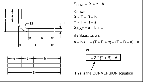
    The equation above would appear in a table as shown in the illustration Example of Determining a Conversion Equation.

    The variables you can use in a conversion equation are:
    Follow these rules when you enter the conversion equation in a bend table:

    Determining a Conversion Equation

    Determine and apply the bend table values in the following manner:

    1. Bend a known length of flat stock to the 90° L-shape as shown in the above illustration.

    2. Add the measurements X and Y and subtract the original flat stock length from this sum.

    3. Apply this deduction value to determine the developed length for models with common material type, inside bend radius, and material thickness.

    The conversion equation shown on the right is based on the graphic on the left.

    Material Data

    Enter a list of the materials for which a particular bend table is intended.

    Follow these rules when you enter and create materials in a bend table:

    Note that material tables contain a parameter Bend Table. If you enter a bend table in a material table and then assign the material to the part, by choosing Assign from the Mater_Mgmt menu, the system checks that the bend table lists the material. If it does not, the system goes ahead and assigns the specified bend table to the part, but it issues a warning message Part Table Bend Error: The part material does not appear in the bend-table material list.

    If you subsequently try to apply another bend table to the part, by choosing Set from the Bend Tab menu, the system again checks to see if the table lists the assigned material. If it does not, the system rejects the command, and issues the above error message.

    Table Data

    The table data are the bend allowances (A) for specific bend radii and material thickness. The table data and the conversion equation are used together, so make sure that the two together give you the correct results.

    For bend radii and material thicknesses between the values in adjacent cells, a linear interpolation is used.

    Note that the values in the bend tables are independent of the model units. They do not change if you change the model units. For example, you originally create a sheet metal part with the model units set to inches. The sheet metal thickness is 0.25 and the bend radius is 0.5. The system looks up the bend table to find the developed length at the ordinates (0.25, 0.5). If you change the model units to centimeters and keep the model the same size, the thickness of the sheet metal becomes 0.625 and the bend radius 1.270. The system looks up the table to find the developed length at the ordinates (0.625, 1.270).

    Example of Bend Table Data

    Bend Table Menu

    Use the Bend Tab menu to do the following:

    How to Access Pro/TABLE

    Use Pro/TABLE to create or edit your own bend table.

    [protab]

    ...or...

    How To Create a Bend Table within a Session

    1. Choose Define from the BEND TAB menu.

    2. Choose Create from the DEF BTAB menu. Enter the name of the bend table.

      A Pro/TABLE window displays with an outline table in it.

    3. Enter the data into the empty table

      ...or...

      Select File, then Read from the Pro/TABLE pulldown menu to use another bend table as a baseline.

      A dialog box appears and prompts you to enter the full name of the file. After you enter the filename, the system reads in the file from disk and writes it over the current file in session. You can then edit the file.

    4. Choose Save or Exit. The system writes the bend table out to disk, in the current directory.

    How To Edit a Bend Table

    Within a session, you can only edit bend tables created with the current part or applied to the current part.

    1. Choose Define from the BEND TAB menu.

    2. Choose Edit from the DEF BTAB menu.

    3. Choose the bend table from the TBL NAMES namelist menu, which lists all the bend tables that were ever applied to the part or were created when that part was the one currently in session.

      A Pro/TABLE window displays with the selected table in it.

    4. Edit the file.

    5. Choose Save or Exit. The system writes the bend table out to disk, in the current directory.

    How To Apply a Bend Table to a Part

    1. Choose Set Up from the PART menu.

    2. Choose Sheet Metal from the PART SETUP menu.

    3. Choose Bend Allow from the SMT SETUP menu.

    4. Choose Bend Table from the BEND ALLOW menu.

    5. Choose Set from the BEND TAB menu.

    6. Choose Apply from the SET BTAB menu.

    7. Choose Confirm from the CONFIRMATION menu.

    8. Select one of the three supplied bend tables (TABLE1, TABLE2 or TABLE3) from the DATA FILES namelist menu

      ...or...

      Choose Names and enter the name of a bend table file (including the path, if necessary).

    How To Remove a Bend Table from a Part

    The system automatically assigns the previous Y-factor to the part and completely regenerates it so as to update the geometry.

    Bend Order Tables

    You can create bend order tables and display them in sheet metal drawings to document the order and dimensions of bend features. Bend order tables can be updated by reviewing the bend sequence. When a bend order table is stored, the file name is <modelname>.bot. (See Drawings for placing a bend order table in a drawing.)

    Note:

    You cannot create or edit a bend order table on a completely unfolded model.

    Bend Order Menu

    Use the Bend Order menu found under the Smt Setup menu to do the following:

    Show/Edit Menu

    Use the Show/Edit menu to do the following:

    How To Create a Bend Order Table

    1. With a model in the bent condition, choose Sheet Metal from the PART SETUP menu.

    2. Choose Bend Order from the SMT SETUP menu.

    3. Choose Show/Edit from the BEND ORDER menu. The
      GET SELECT menu appears.

    4. In response to the system prompt, select a plane or edge to remain fixed while the model is completely unbent. The model is completely unfolded.

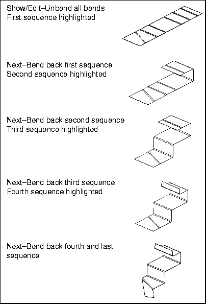
    5. The Add Bend option in the SHOW/EDIT menu is enabled. The GET SELECT menu appears and you are prompted to select the bends for the first sequence. You can select any bend, and any number of bends in any order.

    6. When you have finished adding bends to the current sequence, and you want to start another sequence, choose Next from the SHOW/EDIT menu. The bends in the current sequence are now highlighted in magenta.

    7. In response to the prompt, select a plane which is to remain fixed. The highlighted bends are then bent back.

    8. The Add Bend option in the SHOW/EDIT menu is re-enabled and the GET SELECT menu re-appears. You are now starting a new sequence.

    9. Repeat Steps 6 through 8 until the whole part is bent back.

    10. Choose Done from the SHOW/EDIT menu. The system creates the bend order table.

    Displaying a Bend Order Table

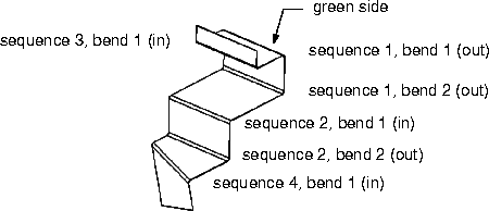
    To write the bend order table to a file and display it on the screen, choose Info from the Bend Order menu. In the bend order table, a bend's direction is considered to be in when it is less than 180° (i.e. acute or obtuse) on the green side. It is considered to be out when it is greater than 180° (i.e. oblique) on the green side. A typical bend order table is shown below.


    This bend order table is based on the completed part below.


    The bend sequences for the part are shown below.


    How To Edit a Bend Order Table

    1. With a model in the folded condition, choose Sheet Metal from the PART SETUP menu, then Bend Order from the SMT SETUP menu.

    2. Choose Show/Edit from the BEND ORDER menu.

    3. In response to the system prompt, select a plane or edge to remain fixed while the model is completely unbent. The model is then completely unfolded.

    4. Bend geometry included in the first bending sequence highlights in magenta. Choose an option from the SHOW/EDIT menu.

    5. Select the bend(s) you want to edit.

    How To Delete a Bend Order Table

    1. With the model in the folded condition, choose Sheet Metal from the PART SETUP menu.

    2. Choose Bend Order from the SMT SETUP menu.

    3. Choose Clear from the BEND ORDER menu.

    Fixed Geometry

    When you are unbending or bending back the part, the system always needs to know which surface or edge is to remain fixed. If you select a surface or edge through the Fixed Geom menu, that geometry is used as the default from then on. If you create an Unbend or Bend Back feature after that, the Feature Window immediately shows that the fixed geometry is defined and you are not asked to select the edge or surface that is to remain fixed.

    Use the Fixed Geom menu found under the Smt Setup menu to do the following:

    How To Access the Default Fixed Geometry

    1. Choose Sheet Metal from the PART SETUP menu.

    2. Choose Fixed Geom from the SMT SETUP menu.

    3. Choose an option to proceed.

    4. Choose Done/Return when you finish accessing the default fixed geometry.

    Default Radius

    When you are creating any kind of feature that contains a bend, the system needs to know the bend radius. Often times, you want to use a default value that might be a function of the material, the material thickness and so on.

    Use the Sel Radius menu found under the Smt Setup menu to do the following:

    From Table Menu

    Choose one of the values in the From Table menu to select a defined default radius. The following is an example of the types of values that you might see in the From Table menu:

    How To Define or Change the Default Radius

    1. Choose Sheet Metal from the PART SETUP menu.

    2. Choose Default Rad from the SMT SETUP menu.

    3. Choose an option to proceed.


    Copyright © 1997 Parametric Technology Corporation
    128 Technology Drive, Waltham, MA 02154 USA
    All rights reserved